Trackside Asset Innovation
Cubis System’s Rail Sector Manager George Woollard discusses lineside electrical asset installation and maintenance.
Trackside electrical equipment can be housed within a variety of enclosures including steel / GRP cabinets, hinged boxes or metal shrouds. If there is variance in this part of the asset, or a particular design is required to accommodate a new development in technology, there is free reign to adjust it.
However, the one element they all have in common is the method of retaining them in the ground which until now, has remained steadfast and universally accepted as being a concrete jigsaw totalling in at around 250kg encircled by a type one and timber edged hardstanding area.
Cubis Systems, the global leader in the design and manufacture of access chambers and cable ducting systems, on investigation of lineside electrical asset installation and maintenance has found weight is not the only problem.
George Woollard, Rail Sector Manager, said other issues include extremely limited working space when cabling, fixed 300mm depth create bend radius issues, no ability to change the cabinet bolt centres or improve the technology substantially as the concrete bases are fixed in dimension, and vermin entering the cabinets.
“In response to the problems we discovered, Cubis Systems formed a working group after a rail demonstration day conducted at sister company NAL’s HQ,” said George.
“It incorporated members of the signals, civils and maintenance disciplines from Network Rail, to provide a broad understanding of what was required to afford maximum benefit for everyone utilising it.
“After IDC style reviews and cross company collaboration with numerous stakeholders, an all-encompassing solution has been produced in the Rail Cabinet Base (RCB).
“The RCB is a lightweight, modular system that removes issues such as those mentioned above and creates a standardised installation method for single pieces of equipment or full suites of assets making this a truly unique and innovative solution.”
It is made from standardised components that feature on all variations which assists in the consistency levels of installation and in turn reduced potential snagging issues.
Product Components
Cabinet Base
The Rail Cabinet Base system is made up of six component parts. See Figure A – (Render exploded view of the system)
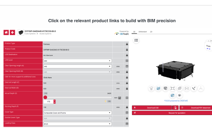
The base/foundation is made from the Cubis STAKKAbox™ ULTIMA Connect Chamber – a modular system comprised of compression moulded GRP, linked together with GRP pegs to form a solid and stable ring. It can also be linked to trackside drainage.
Cabinet Location Modules
These are made from powder-coated aluminium, providing a stable and lightweight interface between the base and the cabinet, which is protected from saline oxidation. A Full LOC case module weighs just 20kg.
Cover and Frame Modules
Between cabinets, lightweight aluminium frames fix to both the base module below and the cabinet modules adjacent to provide strength and stability. Each frame has integral earthing points, so all the modules can be linked together. GRP covers fit into the frame and form the hard-standing area.
Trough Connector
In place of simply butting a piece of trough to the base of the cabinet, a positive location point has been introduced that can be manufactured to fit any size of cable trough required.
Gland Tray
The gland tray fits on top of the Cabinet Location Module and can be pre-fitted with IP rated glands or grommets as per the application requirement, or can be supplied blank to be cut on-site. Easy to upgrade to Plug and Play.
Cover Plate
In place of pallets, ply or bags of cement over the open hole left in the traditional concrete base method whilst waiting for a cabinet to arrive, a purpose-made cover has been introduced.
Installation
A successful trial installation of this system has been conducted at the Swindon Electrification Training School. An RCB2A (two LOC Cabinet Base) was installed by a team in a single shift. For context, a two-cabinet base installed using the standard method takes 2.5 shifts on average to complete with a team of three operatives.
George concluded: “When combined these elements offer far more than a basic foundation for a piece of equipment. There is consideration for the civils teams and the electrical installation, along with maintenance requirements. Above all else the ability to allow management of risk to be simplified and programme times to be reduced.”


